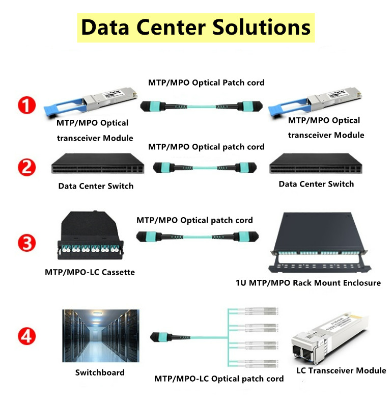
জাম্পার তারগুলি প্যাচ প্যানেল থেকে ট্রান্সসিভারগুলিতে চূড়ান্ত সংযোগ তৈরি করতে ব্যবহৃত হয়, অথবা দুটি স্বাধীন ব্যাকবোন লিঙ্ককে সংযুক্ত করার উপায় হিসাবে সেন্ট্রালাইজড ক্রস সংযোগে ব্যবহৃত হয়।অবকাঠামো সিরিয়াল বা সমান্তরাল কিনা তার উপর নির্ভর করে LC সংযোগকারী বা MTP সংযোগকারীগুলির সাথে জাম্পার তারগুলি উপলব্ধ।সাধারনত, জাম্পার তারগুলি হল ছোট দৈর্ঘ্যের অ্যাসেম্বলি কারণ তারা একই র্যাকের মধ্যে দুটি ডিভাইসকে সংযুক্ত করে, তবে কিছু ক্ষেত্রে জাম্পার তারগুলি দীর্ঘ হতে পারে, যেমন "সারির মাঝখানে" বা "সারির শেষ" বিতরণ আর্কিটেকচার।
RAISEFIBER জাম্পার ক্যাবল তৈরি করে যা "ইন-র্যাক" পরিবেশের জন্য অপ্টিমাইজ করা হয়।জাম্পার তারগুলি প্রচলিত অ্যাসেম্বলির চেয়ে ছোট এবং আরও নমনীয় এবং সংযোগ সর্বোচ্চ প্যাকিং ঘনত্ব এবং সহজ, দ্রুত অ্যাক্সেসের অনুমতি দেওয়ার জন্য ডিজাইন করা হয়েছে।আমাদের সমস্ত জাম্পার ক্যাবলে বেন্ড অপ্টিমাইজড ফাইবার থাকে যাতে টাইট বেন্ডিং অবস্থায় বর্ধিত কর্মক্ষমতা থাকে এবং আমাদের কানেক্টরগুলি কালার কোডেড এবং বেস টাইপ এবং ফাইবার টাইপের উপর ভিত্তি করে চিহ্নিত করা হয়।
• ফাইবার-গণনা দ্বারা রঙিন কোডেড সংযোগকারী বুট
• আল্ট্রা কমপ্যাক্ট তারের ব্যাস
• বাঁক অপ্টিমাইজড ফাইবার এবং নমনীয় নির্মাণ
• 8Fiber, -12Fiber বা -24Fiber ধরনের হিসাবে উপলব্ধ৷
MTP ফাইবার সিস্টেম হল পণ্যগুলির একটি সত্যিকারের উদ্ভাবনী গ্রুপ যা ফাইবার অপটিক নেটওয়ার্কগুলিকে নতুন সহস্রাব্দে নিয়ে যায়।MTP ফাইবার এবং MTP সমাবেশগুলি MTP "মাল্টি-ফাইবার টার্মিনেশন পুশ-অন" সংযোগকারী থেকে তাদের নাম নেয়, যা MPO সংযোগকারীগুলির একটি উচ্চ কার্যকারিতা সংস্করণ হিসাবে ডিজাইন করা এবং প্রবর্তিত হয়।MTP এমপিও সংযোগকারীর সাথে আন্তঃসংযোগ করে।প্রতিটি এমটিপিতে 12টি ফাইবার বা 6টি ডুপ্লেক্স চ্যানেল রয়েছে একটি সংযোগকারীর মধ্যে যা বর্তমানে ব্যবহৃত বেশিরভাগ ডুপ্লেক্স সংযোগের চেয়ে ছোট।MTP সংযোগকারীগুলি টেলিযোগাযোগ কক্ষে নেটওয়ার্ক সরঞ্জামগুলির মধ্যে উচ্চ-ঘনত্বের সংযোগের অনুমতি দেয়।এটি একটি SC সংযোগকারীর আকারের সমান কিন্তু যেহেতু এটি 12টি ফাইবার মিটমাট করতে পারে, তাই এটি ঘনত্বের 12 গুণ পর্যন্ত প্রদান করে, যার ফলে সার্কিট কার্ড এবং র্যাক স্পেসে সঞ্চয় হয়।
মাল্টি-ফাইবার সংযোগকারী সহ MTP প্রযুক্তি ভবিষ্যতের প্রয়োজনীয়তাগুলি পরিচালনা করার জন্য ডেটা সেন্টারে উচ্চ-পারফরম্যান্স ডেটা নেটওয়ার্ক স্থাপনের জন্য আদর্শ শর্ত সরবরাহ করে।এই প্রযুক্তিটি 40/100 গিগাবিট ইথারনেট সহ নেটওয়ার্ক অপারেশনে স্কেলিং এবং স্থানান্তরকে সহজ এবং আরও দক্ষ করে তোলে।বাজারে এখন অনেক MTP পণ্য রয়েছে, যেমন MTP ফাইবার কেবল, MTP সংযোগকারী,
কেবল ব্যবস্থাপনা: ডাটা সেন্টারে এমটিপি মডিউল এবং হারনেস
প্রথাগত অপটিক্যাল কেবল ম্যানেজমেন্ট যেমন ডুপ্লেক্স প্যাচ কর্ড এবং ডুপ্লেক্স সংযোগকারী সমাবেশগুলি অ্যাপ্লিকেশন-নির্দিষ্ট, কম-পোর্ট-গণনা পরিবেশে ভাল কাজ করে।কিন্তু পোর্টের স্কেল ঊর্ধ্বমুখী হওয়ায় এবং সিস্টেম ইকুইপমেন্টের টার্নওভার ত্বরান্বিত হওয়ায় এই ক্যাবল ম্যানেজমেন্ট অব্যবস্থাপনাযোগ্য এবং অবিশ্বস্ত হয়ে ওঠে।ডেটা সেন্টারে একটি মডুলার, হাই-ডেনসিটি, এমটিপি-ভিত্তিক স্ট্রাকচার্ড তারযুক্ত ক্যাবলিং সিস্টেম স্থাপন করা ডেটা সেন্টারের চাল, যোগ এবং পরিবর্তন (MACs) এর প্রতিক্রিয়া উল্লেখযোগ্যভাবে বৃদ্ধি করবে।এই ব্লগে MTP মডিউল এবং MTP harnesses সম্পর্কে জ্ঞান প্রদান করা হবে।
MTP মডিউল এবং harnesses পরিচিতি
একটি MTP-ভিত্তিক অপটিক্যাল নেটওয়ার্ক স্থাপনের একটি সুস্পষ্ট সুবিধা হল সিরিয়াল এবং সমান্তরাল উভয় সংকেত প্রেরণ করার নমনীয়তা।এমটিপি থেকে ডুপ্লেক্স সংযোগকারী ট্রানজিশন ডিভাইস যেমন মডিউল এবং জোতা সিরিয়াল যোগাযোগের জন্য এমটিপি ট্রাঙ্ক অ্যাসেম্বলিতে প্লাগ করা হয়।MTP মডিউলগুলি সাধারণত নিম্ন-পোর্টকাউন্ট ব্রেক-আউট অ্যাপ্লিকেশন যেমন সার্ভার ক্যাবিনেটে ব্যবহৃত হয়।MTP harnesses তারের ঘনত্ব একটি উল্লেখযোগ্য বৃদ্ধি প্রদান করে এবং উচ্চ পোর্ট গণনা ব্রেক-আউট পরিস্থিতিতে যেমন SAN ডিরেক্টরস মান খুঁজে.সমাধানের অন্তর্নির্মিত মডুলারিটি বর্তমান এবং ভবিষ্যতের নেটওয়ার্কিং প্রয়োজনীয়তা মেটাতে কেবলিং পরিকাঠামো সহজে কনফিগার এবং পুনরায় কনফিগার করার নমনীয়তা প্রদান করে।MTP হার্নেস এবং মডিউলগুলিকে দ্রুত ডেটা সেন্টার MAC-এর সাথে মানিয়ে নিতে ব্যাকবোন নেটওয়ার্ক থেকে আদান-প্রদান বা সম্পূর্ণরূপে সরানো যেতে পারে।
ডেটা সেন্টারে MTP মডিউল
এমটিপি মডিউলগুলি সাধারণত ক্যাবিনেট র্যাক ইউনিট স্পেসে অবস্থিত একটি হাউজিংয়ে স্থাপন করা হয়।এখানে MTP ট্রাঙ্ক কেবলটি মডিউলের পিছনে প্লাগ করা হয়েছে।ডুপ্লেক্স প্যাচ কর্ডগুলি মডিউলের সামনের অংশে প্লাগ করা হয় এবং সিস্টেম সরঞ্জাম পোর্টে পাঠানো হয়।ডাটা সেন্টার ক্যাবিনেটে MTP মডিউল ক্যাবলিং সলিউশন একীভূত করা ডাটা সেন্টার ক্যাবলিং অবকাঠামোর স্থাপনা এবং অপারেশনকে উন্নত করতে পারে।নীচের চিত্রে দেখানো হয়েছে, এমটিপি মডিউলগুলিকে ক্যাবিনেটের উল্লম্ব ম্যানেজার স্পেসে একীভূত করা ডাটা সেন্টার ইলেকট্রনিক্সের জন্য উপলব্ধ র্যাক ইউনিটের স্থানকে সর্বাধিক করে তোলে।MTP মডিউলগুলি ক্যাবিনেটের পাশে সরানো হয় যেখানে তারা ক্যাবিনেট ফ্রেম এবং সাইড প্যানেলের মধ্যে স্থাপন করা বন্ধনীতে স্ন্যাপ করে।সঠিকভাবে ইঞ্জিনিয়ারড সমাধানগুলি প্যাচ কর্ড রাউটিংকে সর্বোত্তম সুবিধা দেওয়ার জন্য ক্যাবিনেট র্যাক ইউনিট স্পেসের মধ্যে স্থাপিত লো-পোর্ট-কাউন্ট সিস্টেম সরঞ্জামগুলির সাথে MTP মডিউলগুলিকে সারিবদ্ধ করার অনুমতি দেবে।
MTP/MPO মাল্টি-ফাইবার কেবল সলিউশনের পোলারিটি উন্মোচন করুন
40G এবং 100G নেটওয়ার্কের ব্যাপক স্থাপনার সাথে, উচ্চ-ঘনত্বের MTP/MPO তারের সমাধানগুলি আরও বেশি জনপ্রিয় হয়ে উঠছে।প্রথাগত 2-ফাইবার কনফিগারেশন LC বা SC প্যাচ কর্ডের বিপরীতে, একটি পাঠান এবং একটি রিসিভ সহ, মাল্টিমোড ফাইবারগুলির উপর 40G এবং 100G ইথারনেট বাস্তবায়ন একাধিক সমান্তরাল 10G সংযোগ ব্যবহার করে যা একত্রিত হয়।40G পাঠাতে চারটি 10G ফাইবার ব্যবহার করে এবং চারটি 10G ফাইবার গ্রহণ করে, যখন 100G প্রতিটি দিকে দশটি 10G ফাইবার ব্যবহার করে।MTP/MPO কেবল একটি সংযোগকারীতে 12 বা 24টি ফাইবার ধারণ করতে পারে, যা 40G এবং 100G নেটওয়ার্কে আপগ্রেড করতে ব্যাপকভাবে সুবিধা দেয়।যাইহোক, যেহেতু অনেক ফাইবার আছে, তাই MTP/MPO তারের পোলারিটি ম্যানেজমেন্ট একটি সমস্যা হতে পারে।

MTP/MPO সংযোগকারীর গঠন
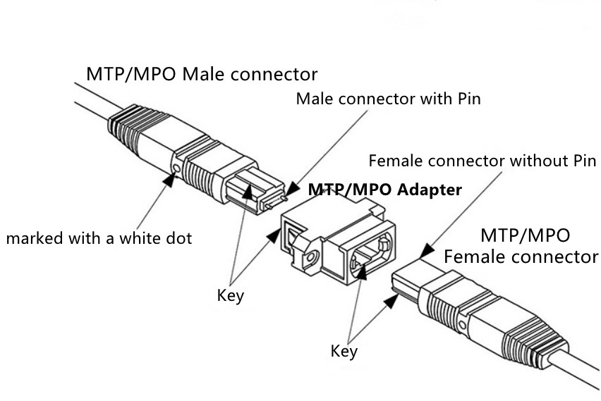
পোলারিটি ব্যাখ্যা করার আগে, প্রথমে MTP/MPO সংযোগকারীর গঠন সম্পর্কে জানা গুরুত্বপূর্ণ।প্রতিটি MTP সংযোগকারীর সংযোগকারী বডির একপাশে একটি কী থাকে।যখন কীটি উপরে বসে তখন এটিকে কী আপ পজিশন হিসাবে উল্লেখ করা হয়।এই অভিযোজনে, সংযোগকারীর প্রতিটি ফাইবার গর্ত বাম থেকে ডানে ক্রমানুসারে সংখ্যাযুক্ত।আমরা এই সংযোগকারী ছিদ্রগুলিকে অবস্থান হিসাবে উল্লেখ করব, বা P1, P2, ইত্যাদি। প্রতিটি সংযোগকারীকে অতিরিক্তভাবে সংযোগকারীর বডিতে একটি সাদা বিন্দু দিয়ে চিহ্নিত করা হয় যাতে সংযোগকারীর অবস্থান 1 পাশে থাকে যখন এটি প্লাগ ইন করা হয়।

MTP/MPO মাল্টি-ফাইবার ক্যাবলের তিনটি পোলারিটি
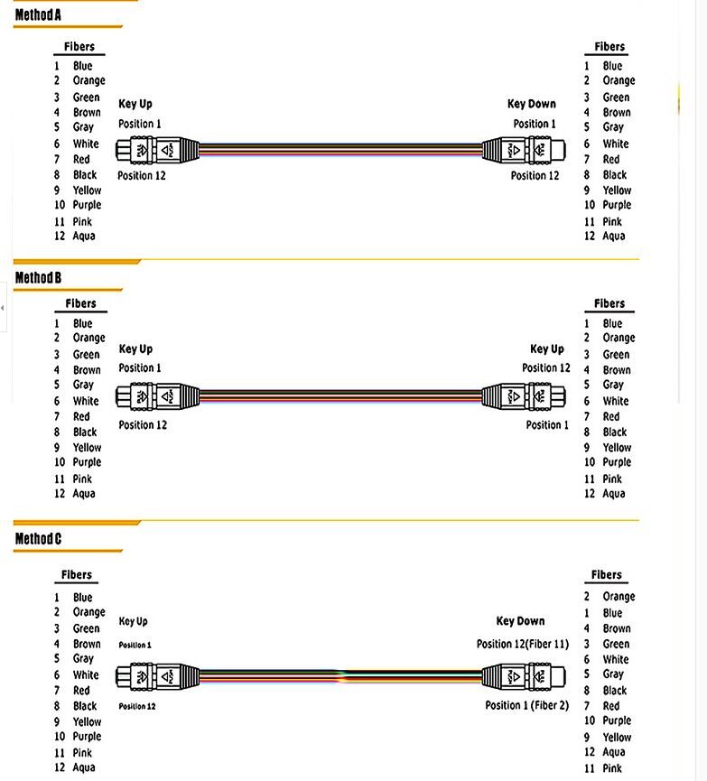
প্রথাগত ডুপ্লেক্স প্যাচ তারের বিপরীতে, এমটিপি/এমপিও তারের জন্য তিনটি পোলারিটি রয়েছে: পোলারিটি এ, পোলারিটি বি এবং পোলারিটি সি।
ছবিতে দেখানো হিসাবে

পোলারিটি এ
পোলারিটি এ এমটিপি তারগুলি একটি কী আপ, কী ডাউন ডিজাইন ব্যবহার করে।অতএব, একটি সংযোগকারীর অবস্থান 1 অন্য সংযোগকারীর অবস্থান 1 এর সাথে সঙ্গতিপূর্ণ।কোন পোলারিটি ফ্লিপ নেই।অতএব, যখন আমরা সংযোগের জন্য পোলারিটি A MTP কেবল ব্যবহার করি, তখন আমাদের অবশ্যই এক প্রান্তে AB ডুপ্লেক্স প্যাচ কেবল এবং অন্য প্রান্তে AA ডুপ্লেক্স প্যাচ কেবল ব্যবহার করতে হবে।যেহেতু এই লিঙ্কে, Rx1 অবশ্যই Tx1 এর সাথে সংযুক্ত হবে।যদি আমরা AA ডুপ্লেক্স প্যাচ ক্যাবল ব্যবহার না করি, পোলারিটি A MTP তারের ডিজাইন নীতি অনুসারে, ফাইবার 1 ফাইবার 1 তে প্রেরণ করতে পারে, অর্থাৎ Rx1 Rx1 তে প্রেরণ করতে পারে, যা ত্রুটির কারণ হতে পারে।
পোলারিটি বি
পোলারিটি বি এমটিপি তারগুলি একটি কী আপ, কী আপ ডিজাইন ব্যবহার করে।অতএব, একটি সংযোগকারীর অবস্থান 1 অন্য সংযোগকারীর অবস্থান 12 এর সাথে মিল রয়েছে।অতএব, যখন আমরা সংযোগের জন্য পোলারিটি B MTP তার ব্যবহার করি, তখন আমাদের উভয় প্রান্তে একটি AB ডুপ্লেক্স প্যাচ তার ব্যবহার করা উচিত।যেহেতু কী আপ টু কী ডিজাইন পোলারিটি ফ্লিপ করতে সাহায্য করে, যা ফাইবার 1কে ফাইবার 12-তে প্রেরণ করে, অর্থাৎ Rx1 Tx1 তে প্রেরণ করে।
পোলারিটি সি
পোলারিটি এ এমটিপি তারের মতো, পোলারিটি সি এমটিপি তারগুলিও একটি কী আপ, কী ডাউন ডিজাইন ব্যবহার করে।যাইহোক, তারের মধ্যে, একটি ফাইবার ক্রস ডিজাইন রয়েছে, যা একটি সংযোগকারীর অবস্থান 1 অন্য সংযোগকারীর অবস্থান 2 এর সাথে সামঞ্জস্যপূর্ণ করে তোলে।যখন আমরা সংযোগের জন্য পোলারিটি C MTP কেবল ব্যবহার করি, তখন আমাদের উভয় প্রান্তে একটি AB ডুপ্লেক্স প্যাচ ক্যাবল ব্যবহার করা উচিত।যেহেতু ক্রস ফাইবার ডিজাইন পোলারিটি ফ্লিপ করতে সাহায্য করে, যা ফাইবার 1কে ফাইবার 2 এ প্রেরণ করে, অর্থাৎ Rx1 Tx1 এ প্রেরণ করে।
পোস্টের সময়: সেপ্টেম্বর-০৩-২০২১

